FSP250-50LC |

|
|
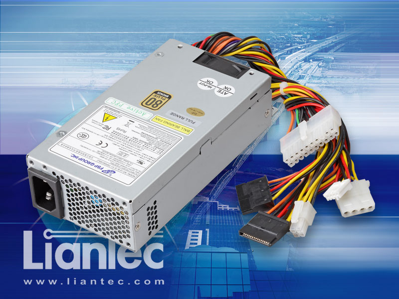
1U Mini-ITX AC/DC ATX 250W Power Supply
|
- Compact Form Factor with 81.5 x 40.5 x 150 mm (W x H x D) of Dimension.
- Full Range 90~264V / 47~63Hz AC Power Input.
- 250 Watts of Continuous Power Output Capacity.
- 17A MAX on +12V DC Output under Continuous Loading.
- 20+4 pin ATX and SATA Power Connector.
- Over 85% of Efficiency under with 50% of Full Loading.
- Under 1 Watt of True Input Power on Standby Mode. EuP Lot-6/2010 Compliant.
- MTBF over 100,000 hours under 100% Loading / 25°C.
- UL+CUL, TUV EN60950-1, CB, CCC, CE, BSMI Certificated.
- Meets 1U and Mini-ITX Platform with ATX Power Requirement.
|

Liantec FSP250-50LC 1U AC/DC ATX Power Supply
Click for Photo Gallery
FSP250-50LC Sample Enquiry
|
|| Overview
| Specification
| Connector and Cable
| Ordering Guide
| Barebone Solution ||
|| Product Image
| Mechanical Drawing (PDF)
| Datasheet (PDF) ||
|
Overview |
|
The Liantec FSP250-50LC 1U Mini-ITX / FlexATX power supply supports full range 90~264V / 47~63Hz AC power input and +5V, +12V, -12V,
+3.3V and +5Vsb ATX power output with 250 watts of power capacity within 81.5 x 40.5 x 150 mm (W x H x D) of dimension, meets the requirement
of x86-based 1U low profile and mini-ITX / FlexATX embedded Small Form Factor (SFF) computing applications. |

|
Specification |
|
Power Input Range
The FSP250-50LC PSU could operate at wide input voltages defined in below table.
Range |
Input |
Min. |
Nom. |
Max. |
Low Range |
V-in (Wrms) / I-in (Arms) |
90 / --- |
100-127 / 3.5 |
135 / --- |
High Range |
V-in (Wrms) / I-in (Arms) |
180 / --- |
200-240 / 2 |
264 / --- |
Frequency (Hz) |
47 |
--- |
63 |
- Inrush current : No component was damaged and input fuse shall not blow.
- Input Fuse Requirement : The PSU shall be protected from primary over current by input fuse.
- Power factor correction greater than 0.9 at full loading.
Power Output Voltage Regulation
The DC output voltages of FSP250-50LC PSU measured at the end of the connectors should be remained within the regulation ranges shown in below table
DC Output |
Min. |
Nom. |
Max. |
Tolerance |
+5V (Volts) |
+4.75 |
+5.00 |
+5.25 |
+5% / -5% |
+12V (Volts) |
+11.4 |
+12.0 |
+12.6 |
+5% / -5% |
-12V (Volts) |
-10.8 |
-12.0 |
-13.2 |
+10% / -10% |
+5Vsb (Volts) |
+4.75 |
+5.00 |
+5.25 |
+5% / -5% |
+3.3V (Volts) |
+3.135 |
+3.30 |
+3.465 |
+5% / -5% |
DC Output Load Current Ranges
The DC output load current is specified as shown in below table. The maximum continuous output power at steady state operating should be
limited at watts. The +5Vsb output should be remained within the regulation limits during the DC fault condition.
DC O/P Load |
Min. (A) |
Nom. (A) |
Max. (A) |
Reak (A) |
+5V (Volts) |
1 |
6 |
12 |
|
+12V (Volts) |
1 |
9 |
17 |
22 |
-12V (Volts) |
0 |
0.25 |
0.50 |
|
+5Vsb (Volts) |
0 |
1 |
2 |
|
+3.3V (Volts) |
0 |
3 |
6 |
|
Max. Combined DC Output
Max continuous DC output power should not exceed 250W at 25°C and de-rating power 1.6W/°C from 25°C to 50°C to get a maximum
continuous power de-rating to 210W at 50°C each output maximum load de-crease in proportion. The total combined 3.3V, 5V power
should not exceed 60W steady state. The total combined 3.3V, 5V, 12V and -12V power should not exceed 240W. The total peak
power should not exceed 300W. The surge duration should be less than 20ms.
DC O/P Load |
Min. (A) |
Nom. (A) |
Max. (A) |
Reak (A) |
+5V (Volts) |
1 |
6 |
12 |
|
+12V (Volts) |
1 |
9 |
17 |
22 |
-12V (Volts) |
0 |
0.25 |
0.50 |
|
+5Vsb (Volts) |
0 |
1 |
2 |
|
+3.3V (Volts) |
0 |
3 |
6 |
|
|
=============================================
|
DC Output |
Combined
Max. Power |
Peak
Max. Power |
|
+3.3V
(Volts) |
250W |
240W |
60W |
300W |
|
+5V (Volts) |
|
+12V (Volts) |
|
|
-12V
(Volts) |
|
+5Vsb
(Volts) |
|
Ripple & Noise
Specification
|
|
+5V |
+12V |
-12V |
+5Vsb |
+3.3V |
|
Ripple & Noise |
50mV |
120mV |
120mV |
50mV |
50mV |
(1)
Ripple & noise test by the oscilloscope bandwidth are
setting at 20MHz.
(2) Add a
0.1µF ceramic disk capacitor in parallel with a 10µF
electrolytic capacitor at output connector terminals for ripple
& noise measurements. If ambient temperature is under 20°C or
over 30°C, the AC input should be nominal input.
Efficiency
The
efficiency of the power supply during normal operating should be
in below table at 115Vac/230Vac line input voltage.
|
Efficiency |
+12V |
+5V |
+3.3V |
-12V |
+5Vsb |
% of Full Load |
|
> 82% |
3.04A |
1.61A |
0.81A |
0.09A |
0.36A |
20% |
|
> 85% |
7.59A |
4.03A |
2.01A |
0.22A |
0.89A |
50% |
|
> 82% |
15.18A |
8.06A |
4.03A |
0.446A |
1.786A |
100% |
Standby Efficiency
At 115Vac,
while in standby mode with a 100mA load on the +5Vsb DC output,
the PSU should draw less than 1 watt of true input power.
Over Voltage Protection
+5V, +3.3V
and +12V output of PSU should be protected from over voltage as
below table..
|
DC Output |
+12V |
+5V |
+3.3V |
|
Max. |
15.6V |
7V |
4.8V |
Environmental
Requirement
Operating
Temperature : 0 to 50°C.
Storage
Temperature : -40 to 70°C.
Operating
Humidity : 20 to 85% related humidity (non-condensing).
Non-Operating
Humidity : 10 to 95% related humidity (non-condensing).
Electromagnetic
Compatibility and Safety Requirements
Conducted EMI
: CE, BSMI, FCC, CISPR 22 class B.
Safety :
UL+CUL, TUV EN60950-1, CB, CCC, CE, BSMI.
Reliability
MTBF : >
100,000 hours under 100% loading / 25°C.
Safety :
UL+CUL, TUV EN60950-1, CB, CCC, CE, BSMI.
Dimension
Body : 81.5 x
40.5 x 150 mm (W x H x D) |